Skip to content
Exact Detailing
Back to Services

Mass Timber

Detailing mass timber since 2011, starting with pioneering projects at the onset of the industry’s modern expansion. Growing alongside the sector's evolution has driven deep technical mastery across mass glulam, CLT, DLT, and complex hybrid timber-steel networks.

Project Workflow:

PROCESS & TIMELINE

Project Workflow:

Our detailing team manages each project through four phases, from initial drawing review through to field support during erection. The model and drawing set are maintained continuously through all four, and the same project manager and detailing team stay on the job from start to finish.

01. Design Review & Coordination

Before modelling begins, our team reviews the architectural and structural drawings to identify missing information, connection ambiguities, and coordination issues that will need to be resolved through RFIs or design-assist input. We also confirm the fabricator's shop standards, preferred connection types, and CNC capabilities. Questions get raised early!

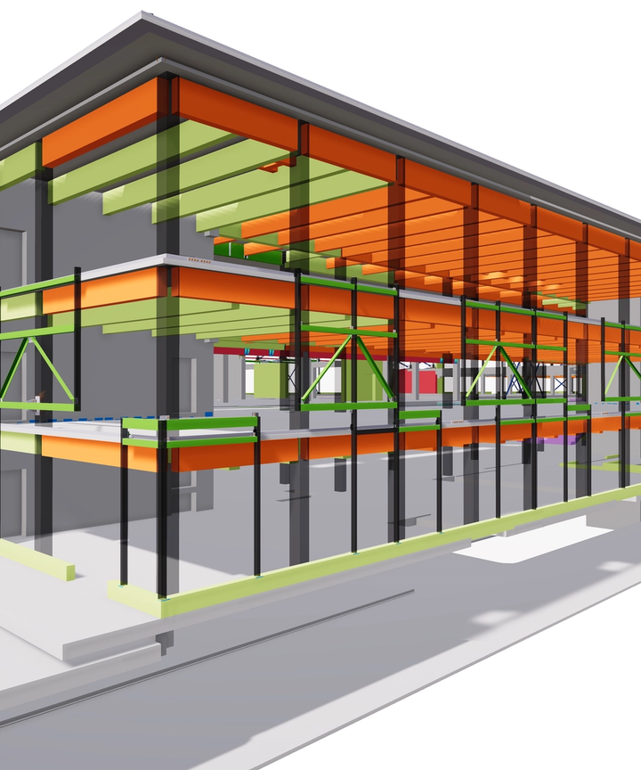
02. 3D Modelling & Panelization

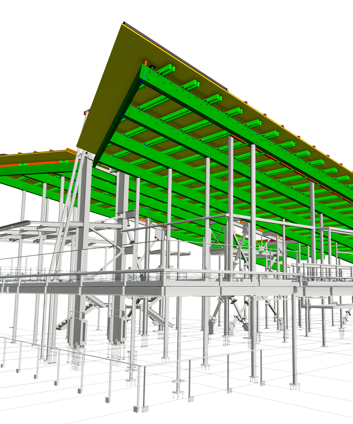
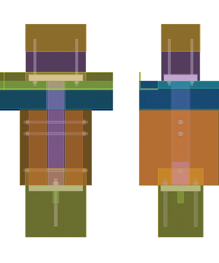
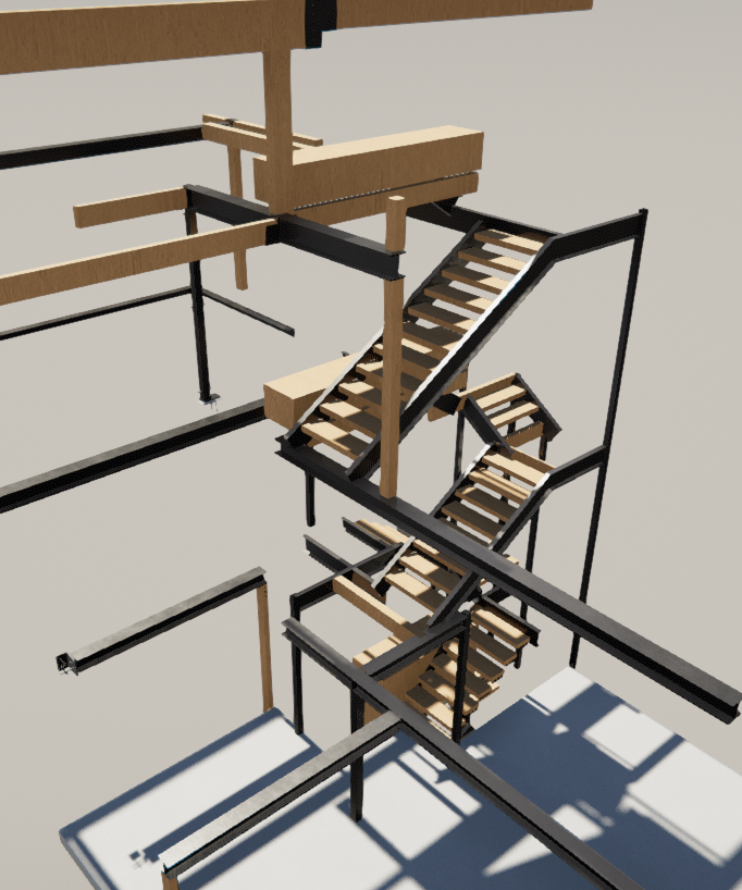
Structural steel members and mass timber panels are modelled in Tekla at full fabrication detail, including connections, hardware, cutouts, and erection sequencing. Our detailers build the model with the shop and field in mind, structuring assemblies and piece marks around how the steel will actually be fabricated, shipped, and erected. The model serves as the single source for all downstream deliverables.

03. Shop Drawing Production

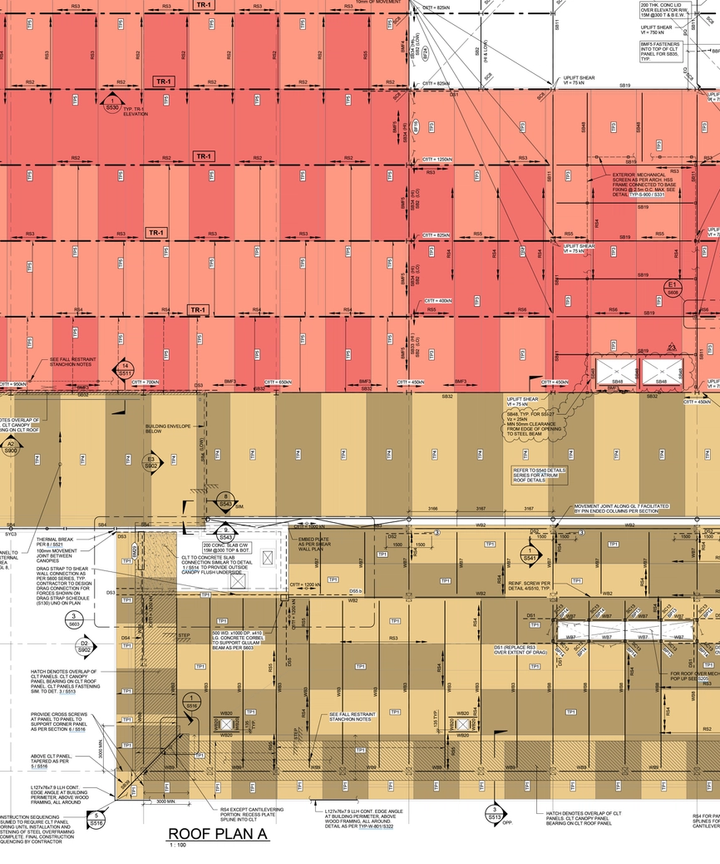
Shop drawings, erection drawings, and material lists are extracted from the coordinated model. Drawing packages are organized by fabrication sequence and area to support the engineer's approval process and the shop's production workflow. Our checkers review every package against the model and the contract documents before it goes out.

04. Field & Installation Support

After drawings are issued, our team stays reachable via phone and email for quick responses, continues to manage revisions, respond to RFIs, and update the model as design changes or field conditions require. We stay with the project through fabrication and erection, keeping the model and drawing set current until the last piece is up.

Structural Sectors

MARKET APPLICATIONS

Structural Sectors

Our mass timber detailing team works across commercial, institutional, residential, and mixed-material project types. Each sector has different coordination requirements, approval processes, and fabrication workflows, and our teams are experienced in all of them.

Mid-Rise Buildings

Multi-storey mass timber and mass-ply residential structures. These projects involve repetitive CLT floor and wall panels across stacked floor plates, where cumulative tolerances between levels need to be tracked and managed through the model. Panelization layouts are coordinated with the timber supplier's production and shipping constraints.

Commercial & Institutional

Public buildings, educational facilities, and corporate offices with exposed glulam framing, long-span roof structures, and architecturally finished timber. These projects typically carry more involved engineering review and approval processes, and the detailing needs to support that from the start with clean, well-documented drawing packages.

Hybrid Timber-Steel Projects

Structures that combine engineered wood with structural steel. Both materials are modelled together in Tekla so that connections between timber and steel are fully coordinated at the interface before either material goes to fabrication. This includes custom steel connector plates, embed details, and hardware that bridges both scopes.

Mission Critical & Data Centres

Facilities that incorporate mass timber or CLT alongside structural steel framing. Timber and steel are modelled in the same environment and coordinated against MEP routing and equipment layouts. These projects are typically fast-tracked, with detailing phased to match an accelerated procurement and erection schedule.

Glulam Detailing & Shop Drawings

COMPONENTS & ASSEMBLIES

Glulam Detailing & Shop Drawings

Structural glulam members are modelled in 3D with camber, grain orientation, and arch geometry represented in the model as they will be fabricated. Steel connection hardware, concealed knife plates, and internal rods are modelled as part of the timber assemblies, so the shop drawings our team produces reflect the complete built condition and are ready for your approval process.

Core Drawings & Submittals

  • Elevations & Cross-Sections: Clear 2D shop views showing exact beam profiles, column heights, and arch geometries with direct fabrication callouts.
  • Camber & Material Parameters: Explicit dimensions for structural camber arcs and grain orientation constraints so the timber is handled and cut correctly.
  • Hardware & Knife Plate Integration: Direct modelling of custom steel connection plates, internal rods, and fastener locations to catch fitment issues before production.
  • Shop Layout Baselines: Dimensioning schemes mapped directly to your shop’s reference lines for straightforward manual layout and verification.
  • Piece Marks & Erection Notes: Clean piece-marking and assembly instructions to track members from the storage yard straight to the crane hook.
CLT Panel Detailing

MASS TIMBER SYSTEMS

CLT Panel Detailing

CLT panels are modelled in Tekla at full fabrication detail before production begins. Panel geometry includes half-laps, spline joints, step joints, and MEP penetrations, all dimensioned to the tolerances required by the CNC processing equipment. Drawing packages are organized by billet size and erection sequence to support both the shop's production workflow and the field installation plan.

Field & Erection Packages

  • Erection Sequence & Piece Marks: Panel layouts with piece marking organized to match the erection sequence and site staging plan, so panels can be loaded, shipped, and installed in order.
  • Factory Openings & Routings: Window, door, and MEP penetration locations with pocketing and chase paths dimensioned for CNC processing at the factory.
  • Interface & Edge Details: Half-laps, spline joints, and step joints modelled at panel-to-panel, panel-to-steel, panel-to-glulam, and panel-to-concrete interfaces.
  • Rigging & Lift Point Layouts: Lifting insert and hoist point locations positioned based on panel weight and centre of gravity for safe handling and placement.
  • Billet Yield Optimization: Panel boundaries mapped to your specific master billet sizes to reduce drop and maximize material recovery.
Hybrid Coordination

MULTI-MATERIAL INTERFACES

Hybrid Coordination

Most mass timber projects involve structural steel and concrete in addition to timber. The coordination risk on these projects sits at the interfaces between materials, where separate fabrication shops are producing components that need to fit together on site. We model steel and timber in the same Tekla environment so those interfaces are resolved in the model before either shop starts production.

Coordination & Model Deliverables

  • Interface Resolution: Connection geometry between timber, steel, and concrete elements is modelled and verified across all materials before fabrication data is issued to either shop.
  • Steel-to-Timber Intersections: Glulam-to-steel interfaces, including internal knife plates, concealed hangers, tension rods, and welded assemblies, are modelled as complete assemblies so steel and timber fabrication data is produced from the same geometry.
  • Ledger & Bearing Clearances: CLT panels bearing on steel ledgers or wide-flange beams are modelled with step joints and clearance tolerances accounted for at the connection.
  • Fastener & Bolt Hole Alignment: Bolt patterns in the steel fabrication data are cross-checked against the timber CNC routing paths to confirm alignment between shops.
  • Base Plate & Anchor Bolt Matching: Coordination of timber column base plates with concrete anchor bolt layouts manages foundation clearance tolerances early.
  • Multi-Trade Interface Data: Combined multi-material model data gives the general contractor and both fabrication shops a source of truth to review before manufacturing.

Build for Scale.

REQUEST A QUOTE